|
|
|
Analysis of a conventional 5/8λ base-fed antenna
Examination showed that the 5/8λ radiator, despite it's considered among the best solutions for 10/12m amateur, has some negative factors; one of the most important is the RF current distribution along the radiating element.
Fig.1 shows the current distribution, with its animated simulation, of a classic 5/8λ base-fed antenna; it's evident that about one fifth of the total radiator length radiate out of phase.
This implies an elevation of maximum radiation angle that appears to be between 21° and 24° with a considerable loss of signal on the horizon, on average, 0.9-1.4dB. (See 3D radiation diagram and its section of Fig.2).
|
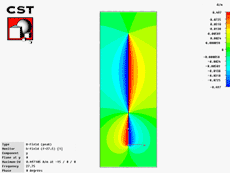
Fig.1 - click to open full size
|
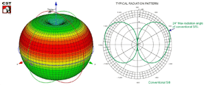
Fig.2 - click to open full size |
Remark:
Some manufacturers claim collinear type antenna or wavelengths not corresponding to the truth.
Please note that more compact colinear configuration at 27MHz, ie 1/2λ above 1/4λ , must be at least 8.3m long without considering the phasing device dimensions.
Our analysis took into account only antennas with physical length of the radiator, excluding bracket and anchoring systems, approximately 6.5 - 6.9m with or without ground plane.
|
How Gain-Master™ works (Patent Pending)
As shown in Fig.3 the RF signal started from the generator run through the coaxial cable of the choke coil, then continue along the first part of the whip until it meet the coaxial stub that works as impedance matching, and then continue up to the termination of the coaxial line (antenna phase centre).
At this point, the signal on the inner conductor crosses the capacitor and propagates along the upper half of the radiation element.
The RF current travelling inside the cable shield, protruding outside the screen and descend toward the choke coil where the high impedance stop it (in fact, it's equivalent to a centre-fed dipole). |
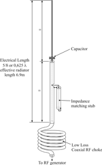
Fig.3 - click to open full size
|
Why Gain-Master™ has better performance compared to a conventional 5/8λ |
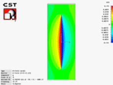
Fig.4 - click to open full size
|
Fig.4 shows the current distribution and animated simulation of SIRIO Gain-Master™.
The new design of radiant element (Patent Pending) behaves as a centre-fed dipole, hence all RF currents are in phase.
This arrangement allowed us to increase the maximum gain of 0.6dB in comparison to a conventional 5/8λ antenna with equal length; also it allowed us to have a radiation pattern similar to a dipole which has its maximum gain on the horizon (See 3D radiation pattern and its section in Fig.5).
Gain-Master™ has the highest available gain for 5/8λ antenna and due to its angle of radiation perfectly horizontal, can improve performance, better than competing antennas, at least 1-2dB, corresponding to 26%-58% more gain, as shown by direct pattern comparison showed in Fig.6 and far-field tests with spectrum analyzer Fig.7.
|
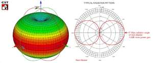
Fig.5 - click to open full size |
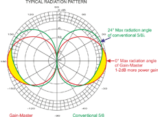
Fig.6 - click to open full size |
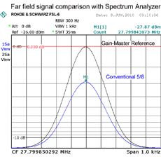
Fig.7 - click to open full size
|
Other Gain-Master™ advantages are:
It does not require ground plane radials because it is a balanced antenna that function as a centre-fed dipole.
It's protected against static discharge by DC-short.
Thanks to it's cable coil (RF-Choke) at the base, Gain-Master™ is fully decoupled from its supporting structure (poles, towers, etc.) with the benefit of preserving both the impedance that the radiation pattern.
It has a exceptionally bandwidth (see Fig.8) of over 4.5MHz from 25.5 to 30MHz and does not requires any tuning.
It accepts a maximum continuous power of 500Watts RMS.
|
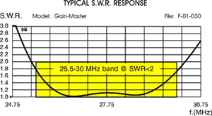
Fig.8 - click to open full size
|
|
|
|
|
| |
|
|

